UML diagrams part 1.
Use case diagram
It is used to capture all the use cases of the actors that interact with the proposed system. Actors include, for example, users or external systems. This diagram also serves as a basis for estimating the size of the proposed system, which allows us to better estimate the overall project.
In some cases, a textual capture is also used where they are described:
- the name of the use case, or an identifying abbreviation
- description
- actors
- priority
- scenario of actions
- etc.
The most important constructs include:
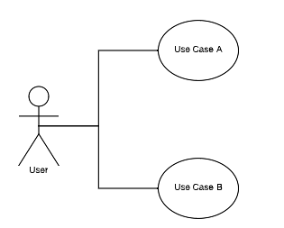
Tento konstrukt popisuje Aktéra (User) a všechny případy užití, které se aktéra týkají.
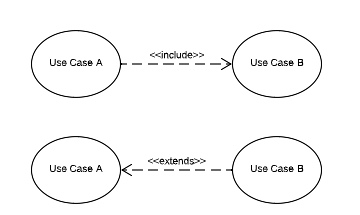
The <<include>> line shows the mandatory extension of Use Case A with Use Case B.
The line <<exclude>> shows the optional extension of Use Case A by Use Case B.
It is also important to follow the direction of the arrows.
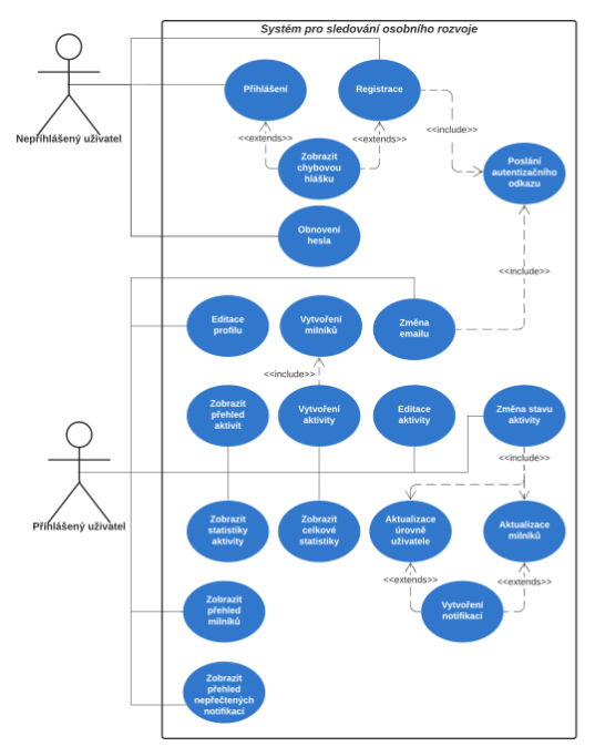
The following figure shows a sample Use Case diagram of a habit tracker application.
Activity diagram
Activity diagram is used to capture the flow of an activity or algorithm design. In some cases, it is used to specify a complex use case. A well-designed activity diagram can help to clarify some parts of the proposed system.
Some of the most important constructs include:
Start and end nodes

Each flow starts at the Start node and ends at the End node
Branch/Merge node
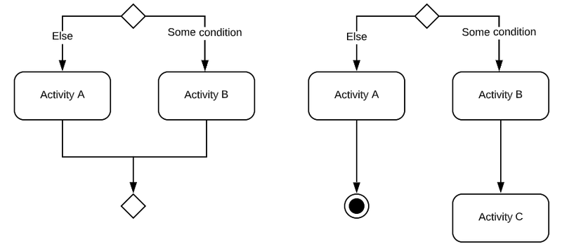
If we use branching, it is important to reconnect the flow of activity at some point.
In the example on the left, the branching is shown where the flow ends if it reaches a certain branch.
Fork/Join node
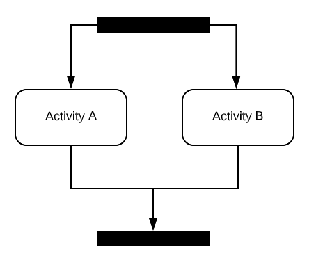
If we need to capture a parallel run in the Activity diagram, the Fork/Join construct is used. It is important to join the parallel runs at some point.
Swimlanes
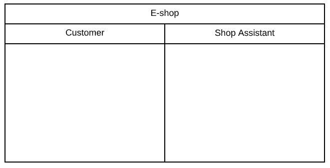
This construct illustrates the zones of responsibility for actors. All constructs in the actor zone belong to that actor.
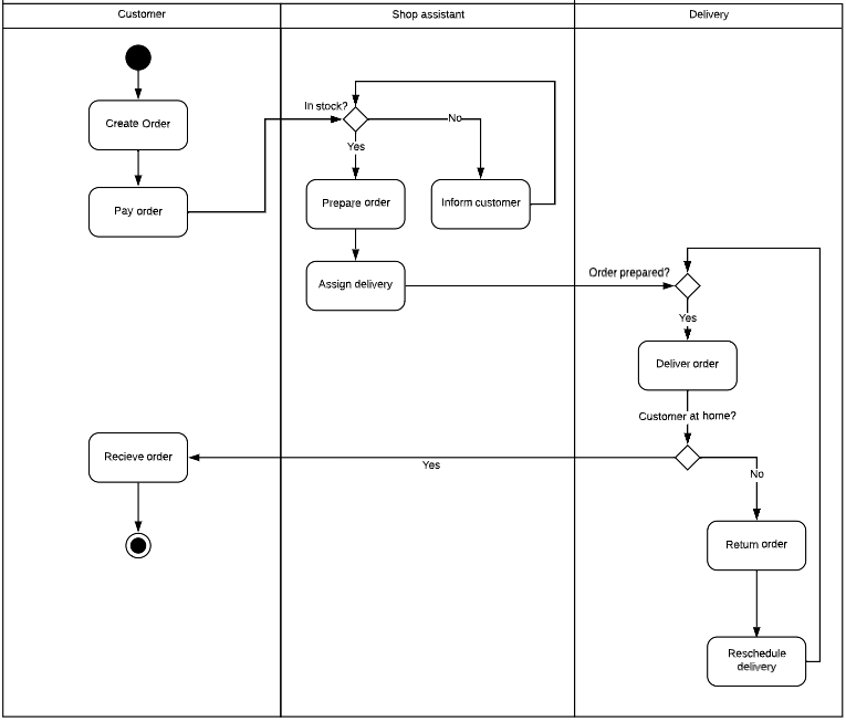
This figure shows the activity of creating an order by a customer to the actual delivery of the e-shop without a brick-and-mortar store and delivering only after online payment.
