UML diagrams part 1.
In many companies there is no standard for design and more emphasis is placed on the implementation itself. This can lead to faster development if the developers themselves are part of the requirements analysis and specification development. In a situation where the teams are separated there are many misunderstandings between the product management and the development team, which slows down development considerably and in the worst cases can lead to a developer vs product manager situation.
In this article, I would like to focus on the Unified Modeling Language (UML) and its most used diagram types. Why this language? It is the most used modeling language, not only in the software development space. Thanks to its formalization and popularity, a paragraph of text can be captured with a single "line" between diagram entities. Another of its advantages is its verifiability and the availability of self-study materials.
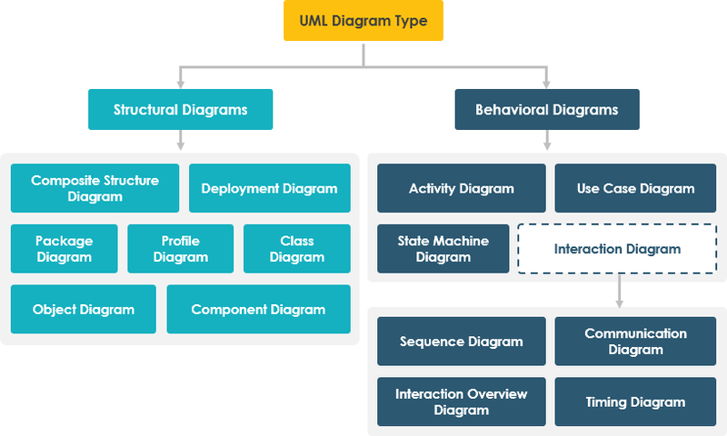
UML diagrams are divided into 2 main categories:
- Structure Diagrams - describe the structure of the system.
- Behaviour Diagrams - describe the behaviour of the system.
- Interaction Diagrams - describe the interaction between individual parts of the system
Class Diagram
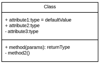
A class diagram is used to further understand the domain, identify entities and their relationship to each other. This diagram can capture a lot of implementation information and is also easy to understand for members outside the development team. It also serves as the basis for the database model.
The first step in designing a class diagram is to identify the entities of the domain for which the software is being developed. Here, individual class attributes and methods can be defined along with their visibility (+ public, - private, # protected)
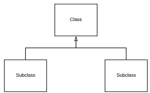
Association, inheritance, aggregation and composition are most commonly used to capture the individual relationships between entities.
Inheritance works classically like class inheritance in object-oriented programming.
The association can be understood as a Foreign key relationship (in a database context)
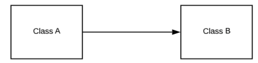
Class A has a structural link to Class B. Or Class A holds a foreign key to Class B.
Aggregation can be thought of as a collection. Or if Class A belongs to Class B. Class A may have a different lifetime than Class B (it may not be created at the same time).
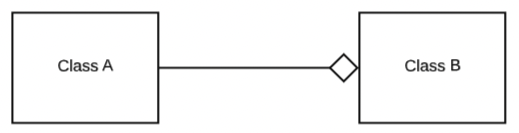
Example:
Class A = tyre, Class B = car.
Class A is created in the summer and in the winter there is a situation of changing from summer tyres to winter tyres. The tire and the car were created at different times.
Composition can be seen as the folding of an object by other objects. It is similar to aggregation, but differs in that the objects disappear together (deleting the parent object also deletes the individual parts).
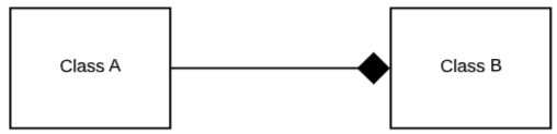
Example:
Class A = Industry, Class B = Company.
When a company disappears, its individual branches also disappear.
Multiplicity
Multiplicity can also be represented for links between objects.
1..* = one to infinity
0..* or * = 0 to infinity
m = m only
m..n = m to n
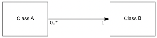
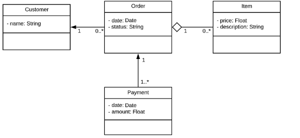
A Class A object can have only one binding to a Class B object. While a Class B object can have 0..* bindings to Class A objects.
The following figure shows a simple example of capturing orders in a UML Class diagram.
State Machine Diagram
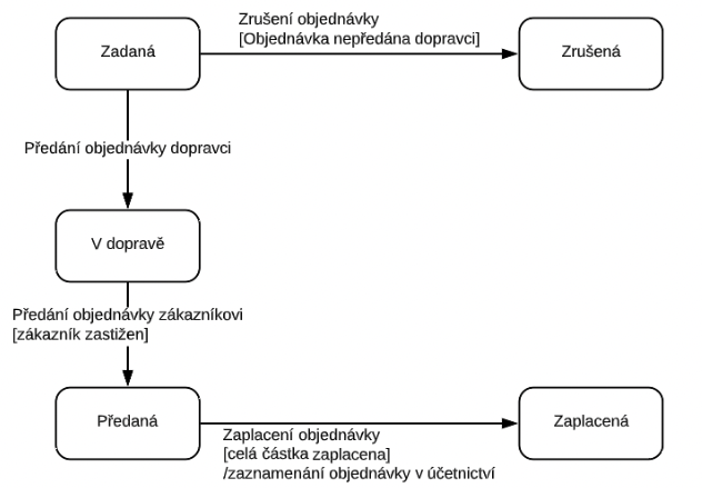
For some entities, the state relevant to the entity is also recorded. A State Machine Diagram is a UML behavioral diagram that should be used to clarify the states of an entity. What states an entity can be in, under what events and conditions an entity can change its state.
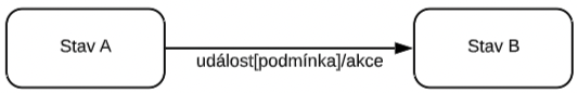
The transition from State A to State B occurs in some event under some condition and action that takes the entity from State A to State B.
The condition and action are optional transition information.
The following figure shows a simple example of capturing the states of an e-shop order without brick-and-mortar store and a claim in a UML State Machine Diagram.